Published date: November 30, 2006
By: Rodney Nieves - Microdesk
Applies to: Autodesk Civil 3D 2007
To drape an image on a Civil 3D surface object, Autodesk Raster Design needs to be installed with Autodesk Civil 3D. This requirement is necessary to insure that the image is placed at the same coordinate system as the surface.
Note: The steps below assume Drawing Settings for “Units and Zone” are already defined and the surface object already exists in the Civil 3D drawing session.
Example of surface object displaying contours built from a point file:
Autodesk Raster Design - Insert and Correlate Image:
The image that is to be draped on the surface object must be inserted into the drawing, and perhaps additionally correlated on the same coordinate system as the surface object.
Using Raster Design, perform the following steps:
• Using the IINSERT command, insert the image.
• If necessary, correlate the image using the Match, Scale, and/or Rubbersheet commands.
• Make sure that the image frame (IFRAME) is toggled ON for future reference.
• If necessary, enter REGEN on the command line to see the image placed behind the surface object.
Example of aerial photo overlay on existing ground surface: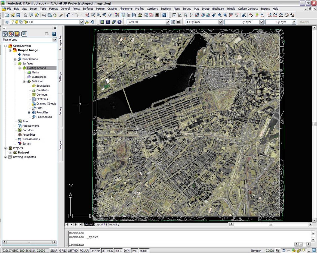
Autodesk Civil 3D – Surface Style:
The surface style that is applied to the surface must be modified to display triangle faces when the surface is displayed in a 3D view.
To modify the Surface Style:
• Right-click the surface object then click “Edit Surface Style…”
• In the Surface Style dialog box, click the “Display” tab.
• On the “Display” tab, select 2D from the View Direction drop-down list. To turn on the Triangles component, click the light bulb in the “Visible” column. You can also turn other components on or off as necessary. This ensures that the surface has 2D faces onto which the image can be draped in subsequent steps.
• On the “Display” tab, select 3D from the View Direction drop-down list. To turn on the Triangles component, click the light bulb in the “Visible” column. You can also turn other components on or off as necessary. This ensures that the surface has 3D faces onto which the image can be draped in subsequent steps.
• In the Surface Style dialog box, click the “Triangles” tab.
• For illustrative purposes, you can decide to adjust the Triangle Display Mode to exaggerate the elevations. (Optional)
• Dock the Render Toolbar to from the available ACAD Toolbars.
Attaching the Image (Material) to the Surface Object:
• On the Render toolbar, click the “Materials…” icon or type the command MATERIALS.
• Within the Materials Editor, select the “Create New Material” button. Enter in a Name and Description for the new material.
• Within the Materials Editor, click the “Select” button to browse for an image to be used as a texture map.
• Within the “Select Image File” dialog box, browse to the location of the image file that will serve as the texture map.
• Click the “Adjust scale/tiling, offset, and rotation values of bitmap” button.
• Within the Adjust Bitmap dialog, proceed to make the necessary adjustments of the image (material) that will be used to drape on to the surface once you have completed the steps outlined in this procedure. For this example, I choose “Fit to object” and I unchecked the “Tiled” option.
Autodesk Civil 3D – Surface Properties:
The Surface Properties that is applied to the surface must be modified to display triangle faces when the surface is displayed in a 3D view.
To modify the Surface Properties:
• Right-click the surface object then click “Surface Properties…”
• In the Surface Properties dialog box, click the “Information” tab.
• On the “Information” tab, select the “Edit Current Selection” from the drop-down arrow for the current “Render Material style”.
• On the “Definition” tab, select the “Material Name” specified in the Create New Material dialog in the preceding instructions. For this example, I used “Aerial Photo”. Apply changes and exit from the Surface Properties.
To set the drawing in a 3D view, use any of the following procedures:
• On the menu bar, click View > 3D Views > SW/SE/NE/NW Isometric command to place the drawing in an isometric view.
• At the command prompt, enter ORBIT on the command line, and then use the orbit jig to place the surface in the desired 3D perspective.
Attaching the Image (Material) to the Surface Object - Continued:
• Within the Materials toolpalette, select the “Apply Material to Objects” button. You will be prompted at the command line to “Select objects”. At this point, type ALL and press the enter key to end the command.
On the Render toolbar, click the “Mapping” icon or type the MATERIALMAP command.
You will be prompted at the command line with:
Select an option [Box/Planar/Spherical/Cylindrical/copY mapping to/Reset mapping]
Select faces or objects:
Select the surface object and press the enter key twice. You then you will be prompted at the command line with:
Accept the mapping or [Move/Rotate/reset/sWitch mapping mode]:
Press the enter key to accept the mapping.
At this point, the image has been mapped to the surface object. The image will drape over the surface when viewed in a 3D isometric view using the RENDER command.
To see a quality rendering of the draped image:
• On the Render toolbar, click the “Preferences..” icon or type the RPREF command.
• In the Advanced Render Settings toolpalette, set the Render Preset drop-down list to “Presentation’ or manually adjust the settings to your desire.
• Close out of the Advanced Render Settings toolpalette.
• On the Render toolbar, click the “Render..” icon or type the RENDER command to render the draped image on the surface object.
Example of surface object before applying RENDER:
Example of rendered draped image on a Civil 3D surface object:
Credits: "Office of Geographic and Environmental Information (MassGIS), Commonwealth of Massachusetts Executive Office of Environmental Affairs".
Data: 1:5,000 Color Ortho Imagery (2005) - April 2005 & Digital Terrain Models (DTMs)

No comments:
Post a Comment